CONDUCTOR CABLE
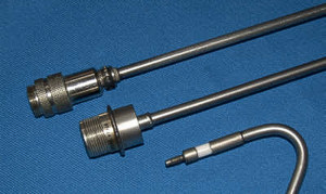 Conductor cable assemblies for normal industrial use to severe service for high temperature, corrosive, and exotic applications.
- Cable assemblies are available with leads or connectors are ready for installation.
- Eliminate the replacement of cables which deteriorate in radiation, severe heat, or corrosive environments.
- Stainless steel sheath construction and MgO insulation provide for exposure up to 1600 °F.
- Cable assemblies are available with hermetically sealed connectors.
- Cables are flexible and are available in several sheath materials, sizes and conductor materials.
- Custom cables can be manufactured to meet your specific requirements.
DESIGNS
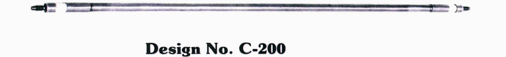
Cable:
- Sheath diameters available from 0.250″ to 0.500″ outside diameter (O.D.).
- Sheath material available in 300 series Stainless Steel or Inconel 600*.
- Magnesium Oxide (MgO) insulation single conductor in 300 series Stainless Steel, Inconel 600*, Nickel Clad Copper, or Copper.
Seal:
- Hermetically sealed AerOpak® cable.
- Connector materials are Nickel with a ceramic insert.
- Voltage rating = 1,500 VDC at 68 °F.
- Maximum operating temperature = 1,600 °F.
AEROPAK® SPECIFICATIONS
Standard Sheath Diameters And Dimensions |
||||||||
|---|---|---|---|---|---|---|---|---|
| ARi Symbol | Sheath Diameter | Wall Thickness | Conductor Diameter | Normal Mfg. Length | ||||
| inch | mm | inch | mm | inch | mm | feet | meters | |
| K | .500 | 12.70 | 0.072 | 1.83 | 0.080 | 2.03 | 30 | 9.1 |
| I | .375 | 9.55 | 0.057 | 1.45 | 0.063 | 1.60 | 55 | 17.0 |
| G | 0.313 | 8.00 | 0.048 | 1.22 | 0.051 | 1.30 | 85 | 26.0 |
| F | 0.250 | 6.35 | 0.038 | 0.97 | 0.042 | 1.07 | 135 | 41.0 |
| E | 0.188 | 4.75 | 0.028 | 0.71 | 0.032 | 0.81 | 240 | 73.0 |
| D | 0.125 | 3.18 | 0.020 | 0.50 | 0.021 | 0.053 | 560 | 171.0 |
Sheath Materials |
|||||
|---|---|---|---|---|---|
| Sheath Material | ARi Symbol | Melting Point | Useable Temp. in Air | ||
| °F | °C | °F | °C | ||
| 347 St/St | F | 2550 | 1400 | 1650 | 900 |
| Inconel 600 (1) | B | 2570 | 1410 | 2100 (2) | 1150 |
| 304 St/St | A | 2550 | 1400 | 1650 (3) | 900 |
| 310 St/St | D | 2570 | 1410 | 2100 | 1150 |
| 316 St/St | C | 2550 | 1400 | 1650 | 900 |
(1) Trademark of International Nickel Corp.
(2) Not recommended for use in sulfur atmosphere.
(3) Do not use in 800 to 1300 °F temperature range due to intergranular precipitation.
Conductor Materials (Symbols And Resistance at 20 °C (68 °F) |
||||||||||
|---|---|---|---|---|---|---|---|---|---|---|
| Conductor Size | mm | 0.50 | 0.56 | 0.66 | 0.81 | 0.96 | 1.00 | 1.30 | 1.62 | 2.03 |
| inch | 0.020 | 0.022 | 0.026 | 0.032 | 0.038 | 0.040 | 0.051 | 0.064 | 0.080 | |
| gauge | 24 | 23 | 22 | 20 | 19 | 18 | 16 | 14 | 12 | |
| Material | ARi Symbol | Resistance, Ω / Meter | ||||||||
| 304 St/St | 304 | 3.50 | 2.90 | 2.20 | 1.40 | 0.98 | 0.88 | 0.54 | 0.34 | 0.21 |
| 347 St/St | 347 | 3.60 | 3.00 | 2.30 | 1.40 | 1.00 | 0.90 | 0.55 | 0.35 | 0.22 |
| Inconel 600 (1) | INC | 5.00 | 4.40 | 3.00 | 2.00 | 1.40 | 1.30 | 0.78 | 0.50 | 0.32 |
| Oxygen Free Copper | CUOFL | 0.083 | 0.068 | 0.050 | 0.032 | 0.023 | 0.021 | 0.013 | 0.008 | 0.005 |
| Nickel Low Carbon | NIL | 0.50 | 0.41 | 0.30 | 0.20 | 0.14 | 0.13 | 0.077 | 0.049 | 0.031 |
| Constantan | AQ | 2.40 | 2.00 | 1.50 | 0.93 | 0.66 | 0.59 | 0.37 | 0.23 | 0.151 |
| Chromel (2) | KP | 3.50 | 2.90 | 2.20 | 1.40 | 0.98 | 0.88 | 0.54 | 0.34 | 0.218 |
| Alumel (3) | AY | 1.50 | 1.20 | 0.92 | 0.58 | 0.41 | 0.37 | 0.23 | 0.14 | 0.091 |
| 27% Ni Clad Copper | INCU27 | 0.13 | 0.10 | 0.073 | 0.040 | 0.035 | 0.031 | 0.019 | 0.012 | 0.008 |
(1) Trademark of International Nickel Corp.
(2) (3) Trademark of Hoskins Mfg. Corp.
MATERIAL SPECIFICATIONS
CONDUCTOR DIMENSIONS |
|||||||||
|---|---|---|---|---|---|---|---|---|---|
| Nominal O.D. | 1-Conductor | 2-Conductors | 3-Conductors | 4-Conductors | |||||
| inch | mm | inch | mm | inch | mm | inch | mm | inch | mm |
| 0.500 | 12.70 | 0.080 | 2.03 | 0.080 | 2.03 | 0.080 | 2.03 | 0.080 | 2.03 |
| 0.375 | 9.55 | 0.063 | 1.60 | 0.063 | 1.60 | 0.063 | 1.60 | 0.063 | 1.60 |
| 0.313 | 8.00 | 0.051 | 1.30 | 0.051 | 1.30 | 0.051 | 1.30 | 0.051 | 1.30 |
| 0.250 | 6.35 | 0.042 | 1.07 | 0.042 | 1.07 | 0.042 | 1.07 | 0.042 | 1.07 |
| 0.188 | 4.75 | 0.032 | 0.81 | 0.032 | 0.81 | 0.032 | 0.81 | 0.032 | 0.81 |
| 0.125 | 3.18 | 0.021 | 0.05 | 0.021 | 0.05 | 0.021 | 0.05 | 0.021 | 0.05 |
NOMINAL CAPACITANCE Pfd / Ft at ROOM TEMP |
|||||||||
|---|---|---|---|---|---|---|---|---|---|
| O.D. | 1-Conductor | 2-Conductors | 3-Conductors | 4-Conductors | |||||
| W-W | W-S | W-W | W-S | W-W | W-S | W-W | W-S | ||
| 0.500 | 12.70 | — | 85.2 | 56.0 | 91.0 | 70.3 | 104.7 | 67.0 | 118.0 |
| 0.375 | 9.55 | — | 83.4 | 54.0 | 89.9 | 64.4 | 99.7 | 64.9 | 115.9 |
| 0.313 | 8.00 | — | 81.9 | 57.8 | 89.2 | 67.7 | 102.8 | 71.5 | 125.7 |
| 0.250 | 6.35 | — | 80.4 | 62.0 | 101.6 | 63.6 | 98.0 | 69.1 | 117.5 |
| 0.188 | 4.75 | — | 79.3 | 60.0 | 85.5 | 60.0 | 91.7 | 65.6 | 110.9 |
| .125 | 3.18 | — | 78.1 | 59.3 | 87.7 | 59.0 | 90.5 | 64.0 | 108.6 |
NOTE: Capacitance Pfd / Ft will not change appreciatively up to 1100 °F (600 °C).
INSULATION RESISTANCE AT 500 VDC IN MEGOHM-FT |
||||||
|---|---|---|---|---|---|---|
| O.D. | TEMP | Number Of Conductors | ||||
| inch | mm | °F | 1 | 2 | 3 | 4 |
| 0.500 | 12.70 | 500 | 100.00 MΩ | 10.00 MΩ | 10.00 MΩ | 10.00 MΩ |
| 1000 | 10.00 MΩ | 1.00 MΩ | 1.00 MΩ | 1.00 MΩ | ||
| 1500 | 0.10 MΩ | 0.01 MΩ | 0.01 MΩ | 0.01 MΩ | ||
| 0.375 | 9.55 | 500 | 100.00 MΩ | 10.00 MΩ | 10.00 MΩ | 10.00 MΩ |
| 1000 | 10.00 MΩ | 1 MΩ | 1 MΩ | 1 MΩ | ||
| 1500 | 0.10 MΩ | 0.01 MΩ | 0.01 MΩ | 0.01 MΩ | ||
| 0.313 | 8.00 | 500 | 100.00 MΩ | 10.00 MΩ | 10.00 MΩ | 10.00 MΩ |
| 1000 | 1.00 MΩ | 0.10 MΩ | 0.10 MΩ | 0.10 MΩ | ||
| 1500 | 0.10 MΩ | 0.01 MΩ | 0.01 MΩ | 0.01 MΩ | ||
| 0.250 | 6.35 | 500 | 10.00 MΩ | 1.00 MΩ | 1.00 MΩ | 1.00 MΩ |
| 1000 | 1.00 MΩ | 0.10 MΩ | 0.10 MΩ | 0.10 MΩ | ||
| 1500 | 0.10 MΩ | 0.01 MΩ | 0.01 MΩ | 0.01 MΩ | ||
| 0.188 | 4.75 | 500 | 10.00 MΩ | 1.00 MΩ | 1.00 MΩ | 1.00 MΩ |
| 1000 | 1.00 MΩ | 0.10 MΩ | 0.10 MΩ | 0.10 MΩ | ||
| 1500 | 0.10 MΩ | 0.01 MΩ | 0.01 MΩ | 0.01 MΩ | ||
| 0.125 | 3.18 | 500 | 10.00 MΩ | 1.00 MΩ | 1.00 MΩ | 1.00 MΩ |
| 1000 | 1.00 MΩ | 0.10 MΩ | 0.10 MΩ | 0.10 MΩ | ||
| 1500 | 0.10 MΩ | 0.01 MΩ | 0.01 MΩ | 0.01 MΩ | ||