RESISTANCE TEMPERATURE DETECTOR SPECIFICATIONS
SELECTION / MATCHING
Completed probes may be matched in pairs to the nearest 0.01 ohm at 0 °C for differential temperature measurements to 0.05 °C
Completed probes may be supplied with selected ice point resistances within a narrow band to eliminate the need for compensation in indicating circuits.
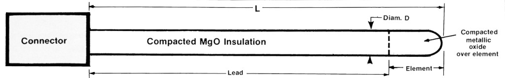
ARi ARiDET® consists of a specially installed platinum resistance element completely encased in compacted metallic oxide insulation of high thermoconductivity to insure minimum temperature differential between the sensor surface and the element. Standard sensors have 3 constantan equi-resistance lead wires in the lead portion with compacted MgO insulation. Sheath material is 316 L ST/ST in fully annealed condition. Performance specifications are shown for the element portion and the lead portion.
RTD |
||||
|---|---|---|---|---|
| LEAD | ELEMENT | |||
| Accuracy | — | ± 0.01 Ω at 0 °C | ||
| Stability* | — | -130 to 93 °C ± 0.05% | -130 to 315 °C ± 0.10% | 315 to 600 °C ± 0.50% |
| Temp Range | -250 to 1000 °C | -200 to 600 °C | ||
| Measuring Current | — | 10 milliamps DC max | ||
| Vibration Shock | Vibration: ± 50G, 60 to 2000 Hz | |||
| Shock: 1000G | ||||
| Along all three mutually perpendicular axes when correctly mounted. | ||||
| Temp/Res. Curve | — | 0.00385 Ω / Ω / °C per DIN 43760 | 0.003916 Ω / Ω / °C per JIS C 1604-81 | |
| Individual Calib. | — | To nearest ± 0.01 Ω at °C | ||
| Self Heating Error | — | Less than 0.02 °C/MW | ||
| Max External Pressure | 50,000 psi (3510 Kg/cm²) | |||
| Stock Length L | 24 inches (610 mm) | |||
*Maximum ice point shift after long term thermal cycling.
SENSOR PARAMETERS |
||||||
|---|---|---|---|---|---|---|
| 1/8″ | 3/16″ | 1/4″ | ||||
| inch | mm | inch | mm | inch | mm | |
| Diameter | 0.125 | 3.18 | 0.188 | 4.78 | 0.250 | 6.35 |
| Temp. Sensitive Length | 1.1 | 28.0 | 1.1 | 28.0 | 1.1 | 28.0 |
| Bending Restriction, Distance from tip to be left straight | 2.1 | 53.3 | 2.1 | 53.3 | 2.1 | 53.3 |
| Minimum Bending Radius | 0.5 | 12.7 | 0.75 | 19.0 | 1.0 | 25.4 |
| Maximum Length | 700 ft | 213 m | 300 ft | 91 m | 175 ft | 53 m |
| Minimum Length | 4 | 102 | 4 | 102 | 4 | 102 |
| Constantan 3-Wire Leads, Resistance in Ω/in each wire | 0.061 | 0.025 | 0.015 | |||
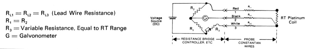
TYPICAL 3-WIRE MEASURING CIRCUIT FOR RTD’S
A 3-wire system may be used to eliminate the effect of lead wire resistance changes by introducing RL (lead wire resistance) into each leg of the bridge. The third lead wire is added to the detector circuit without effecting bridge balance. The resultant circuit is sensitive only to resistance element temperature changes.
TIME RESPONSE CHARATERISTICS
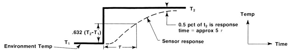
The response of an ARi Resistance Temperature Detector is defined by 2 noticable characteristics when exposed to an instantaneous (step) change in enviroment temperature. These are:
A.) Time Constant (tau). The time to reach 63.2% of the complete step change in temperature.
B.) Response Time. Time to reach within 0.5% of the final temperature in a step change.
This is approximately equal to 5 times the time constant
The response of a temperature sensor to a step change in environment temperature tends to follow a second order differential equation. However, this is approximate, since if the mass of the sensor is small in relation to the mass of the fluid passing over it (such as in the case of a liquid), the response may approach a first order differential equation. A typical response is as follows:
Time constant has application for more common experiences in process control, ie, ramp change or sinusoidal changes in enviromental temperature. The response of a sensor under these conditions are:
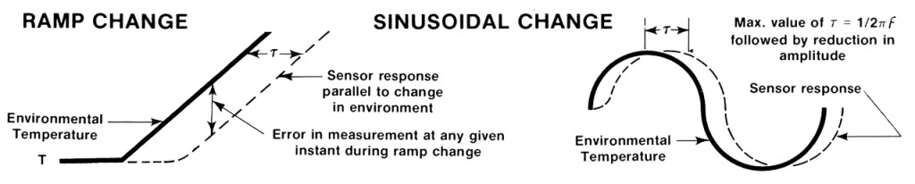
Time constant is related to the environmental conditions by the following approximate relation (Ref NASA TN 2599)
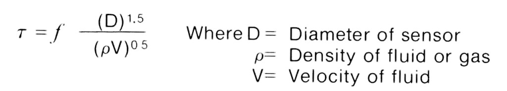
Knowing the time constant for a given sensor at one given set of conditions, it can be computed for another set of conditions.