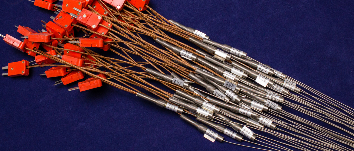
ARi’s standard thermocouple line is used in applications where high reliability is a priority. Our thermocouple line comes with the highest purity MgO insulation to yield maximum EMF stability and minimum drift problems caused by insulation impurities. We have thermocouples available in standard and special calibration limits for types K, J, E, and T per ASTM E-230. Upon request we can also custom manufacture all of our probes to meet your special requirements.
At Ari Industries, we manufacture many of our thermocouples using our own mineral insulated (MI) cable, use of this cable allows for bending of the sheath, and yields very long lengths of finished material. This enables us to supply most of our designs in any length or diameter you require. If you need assistance in choosing a product, our knowledgeable sales staff is always available to help.
Standard Sheath And Wire Diameter |
||||||||||||
|---|---|---|---|---|---|---|---|---|---|---|---|---|
| ARi Symbol | Unit Of Measurement | L | A | B | D | E | F | G | I | K | P | R |
| Sheath Diameter | inches | 0.020 | 0.040 | 0.062 | 0.125 | 0.188 | 0.250 | 0.313 | 0.375 | 0.500 | 0.625 | 0.750 |
| mm | 0.50 | 1.00 | 1.67 | 3.17 | 4.75 | 6.35 | 8.00 | 9.52 | 12.70 | 15.90 | 19.10 | |
| Wire Diameter | inches | 0.004 | 0.006 | 0.10 | 0.020 | 0.032 | 0.040 | 0.051 | 0.064 | 0.091 | 0.114 | 0.120 |
| mm | 0.10 | 0.15 | 0.025 | 0.50 | 0.85 | 1.00 | 1.45 | 1.63 | 2.31 | 2.90 | 3.05 | |
| Maximum Length | feet | 30 | 200 | 290 | 290 | 135 | 81 | 45 | 30 | 30 | 20 | 13 |
| meters | 9 | 61 | 88 | 88 | 41 | 25 | 14 | 9 | 9.1 | 6.1 | 4.0 | |
Wire Calibration (Special Limits Of Error) |
||||||
|---|---|---|---|---|---|---|
| Calibration Type | ASTM E-230 Symbol | ARi Symbol | Similar Calibrations | |||
| Chromel P-Alumel | K | KS | BS 1827 | DIN 43710 | NFE 18-001 | JIS-C1602 |
| Iron-Constantan | J | JS | BS 1829 | NFE 18-001 | — | — |
| Chromel P-Constantan | E | ES | — | — | — | — |
| Copper Constantan | T | TS | BS 1828 | DIN 43710 | NFE 18-001 | JIS-C1602 |
Measuring Junction Symbols |
||
|---|---|---|
| Exposed | Grounded | Ungrounded |
 |
 |
 |
Standard Sheath Materials |
||||||
|---|---|---|---|---|---|---|
| Sheath | ARi Symbol | Melting Point | Useable Temp In Air | Equivalent Analysis | ||
| °F | °C | °F | °C | |||
| AISI 347 ST/ST | F | 2550 | 1400 | 1650 | 900 | BS 3605 832Nb; DIN 4550; UNS S34700 |
| INCONEL 600 (3) | B | 2570 | 1410 | 2100 (1) | 1150 | BS 3074-NA14; DIN 4816; UNS NO6600 |
| AISI 304 ST/ST | A | 2550 | 1400 | 2100 | 1150 | BS 3605-801; DIN 4301; UNS S30400 |
| AISI 310 ST/ST | D | 2570 | 1410 | 2100 | 1150 | BS 3605-805; DIN 4301; UNS S30400 |
| AISI 316 ST/ST | C | 2550 | 1400 | 1650 | 900 | BS 3605-845; DIN 4401; (2-3% Mo); UNS S31600 |
| HASTELLOY X | V | 2470 | 1355 | 2200 | 1222 | Trademark of Cabot Corp. |
(1) Not recommended for use in sulfur atmosphere.
(2) Do not use 800 to 1600 °F temperature range due to carbon intergranular precipitation.
(3) Trademark of International Nickel Corp.
Time Constant |
Some typical time constants (time for thermocouple temperature to reach 63.2% of step change in gas or liquid temperature) for various sizes are listed for different media. |
|||
|---|---|---|---|---|
| Sheath Diameter | Condition (A) | Condition (B) | Condition (C) | Condition (D) |
| (inch) | (seconds) | (seconds) | (seconds) | (seconds) |
| 5/16 | 0.5 | 5.5 | 5.0 | 55.0 |
| 1/4 | 0.3 | 4.0 | 2.5 | 39.0 |
| 3/16 | 0.2 | 2.5 | 2.0 | 26.0 |
| 1/8 | 0.1 | 1.5 | 1.0 | 14.0 |
| 1/16 | 0.05 | 0.5 | 0.5 | 5.0 |
| 1/25 | 0.01 | 0.3 | 0.1 | 2.5 |
Condtion A: No. 7 hot junction in water moving at a velocity (Vo) of 1.5 m/sec (5 ft/sec)
Condtion B: No. 8 hot junction in water moving at a velocity (Vo) of 1.5 m/sec (5 ft/sec)
Condition C: No. 7 hot junction in air moving at a mass velocity (Go) of 29.3 Kg/sec ² (6 lbs/sec ft²)
Condition D: No. 8 hot junction in air moving at a mass velocity (Go) of 29.3 Kg/sec ² (6 lbs/sec ft²)
For time constants (r) at other velocities (V) or mass velocities (G) use the following equations:
The result of these equations will be affected by using liquids other than water and gases other than air. However, the effect is small and can be neglected for many applications.
Insulation Material
Symbol “N” 99.4% minimum high purity MgO meeting requirements of ASTM E-585 and E-608. Impurities are minimized to yield maximum EMF stability and minimum drift problems.
Lead Wire Length “L”
16 inch (40cm) long lead length is normally supplied. If longer lengths are required, please designate in part number.
Insulation Resistance
1000 meg-ohms or more at 500 VDC, for diameters less than 1.6mm (1/16″) 1000 meg-ohms minimum at 50 VDC.
Insulation Bend Resistance
Minimum insulation resistance, after bending around a mandrel whose diameter is 4 times, the sheath diameter, will not change.
High Temperature Insulation Resistance
All AerOpak® thermocouple lengths of 61cm (24″) or less will have a minimum insulation resistance of 10,000 ohms or more at 1 1/2 VDC at 1000ºC (1800ºF).
Availability
2 wire (1 T/C circuit) sheath diameters: 0.50 to 19.1mm (0.020″ to 0.750″).
4 wire (2 T/C circuits) sheath diameters: 3.17 to 19.1mm (0.125″ to 0.750″).
All thermocouples are available with exposed, grounded, or un-grounded measuring junctions.
Specifications
Thermocouples can be made to meet specific customer requirements, or to specifications such as, RDT C7-6T, ASTM E-235, ASTM E-585 or E-608.
Pressure Rating
AerOpak® thermocouples using number 8 or 9 measuring junctions are pressure tight to 3500 Kg/cm2 (50,000 psi) at temperatures up to 649ºC (1200ºF). AerOpak® thermocouples using number 7 measuring junctions are pressure tight to 350 Kg/cm2 (50,000 psi) if a seal is used at the cold end.